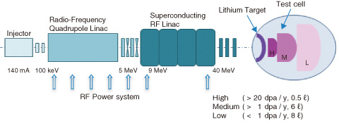
Fig.4-13 Configuration of IFMIF
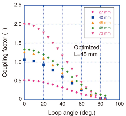
Fig.4-14 Measured results of RF coupling; RF coupling vs. loop angle for the inserted depth
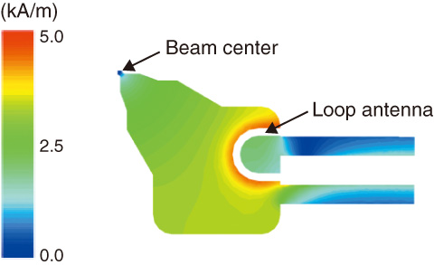
Fig.4-15 Magnetic field profile by 3-D simulation code
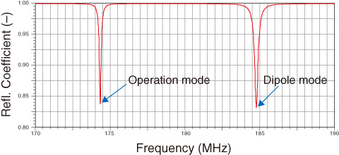
Fig.4-16 Reflection coefficient from RFQ
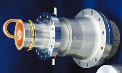
Fig.4-17 Photograph of loop antenna tip module employing an advanced Japanese technology
To realize a demonstration fusion reactor, it is indispensable to evaluate the feasibility for use in fusion reactor materials using 14 MeV neutron irradiation. For this purpose, the International Fusion Materials Irradiation Facility (IFMIF) is being jointly planned by Japan and the European Union under the agreement of Broader Approach Activities agreement.
In the IFMIF, a neutron field is produced by the deuteron (D)-lithium (Li) stripping reaction. The realization of a deuteron beam that can be accelerated and injected into liquid lithium is a key issue (Fig.4-13). In this accelerator facility, two 125mA beam lines are used. Continuous wave (CW) operation is also required, and this is the world’s first attempt at developing such a high-current beam and a CW operation linac. One beam line consists of an ion injector, a radio frequency quadrupole (RFQ) linac and a superconducting RF (SRF) linac; their designed output energies are 0.1, 5.0 and 40 MeV, respectively. We developed a new RFQ, because the RFQ had many technical issues to be overcome for the realization of high-current and CW operation.
In this RFQ linac, a driving RF power of 1.4 MW at 175 MHz has to be injected to the RFQ cavity to accelerate a large current of 125 mA in CW mode. For stable and continuous RF power driving, it is indispensable to reduce the deformation of the loop antenna and to avoid frequency shifts in the operation mode. For this purpose, it is crucial to obtain an RF design by employing a small loop antenna and a short insertion depth.
In this study, the precise RF properties (Fig.4-14) were evaluated by measuring a real size RFQ mock-up module and analyzing a 3-D simulation code (Figs.4-15, 4-16). The insertion depth was successfully optimized. For the world’s first attempt, an engineering design with cooling water channels in the loop antenna was also developed. To make uniform cooling channels following the loop’s curve, an advanced Japanese technology using uniform minute grains of sand was applied. As a result, the loop antenna tip module with cooling channels was successfully manufactured (Fig.4-17). With these results, the development of a loop antenna for CW operation is now in sight.

