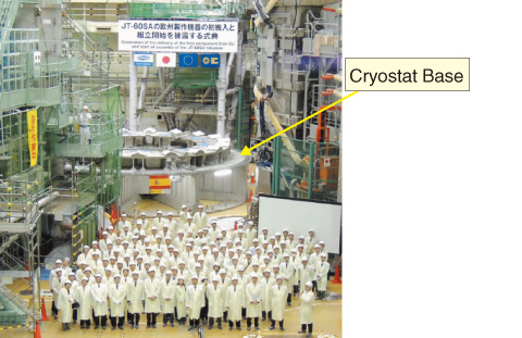
Fig.4-18 Start of assembly of cryostat base
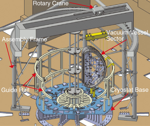
Fig.4-19 Assembly frame for assembly of JT-60SA tokamak
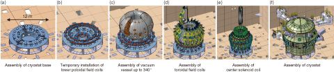
Fig.4-20 Major assembly sequence of JT-60SA tokamak
The design and fabrication of components for the Satellite Tokamak Program (JT-60SA), jointly implemented by Europe and Japan, is progressing well toward the goal of first plasma in March 2019. Disassembly of the JT-60U tokamak at the Naka Fusion Institute was completed in October 2012 on schedule. The assembly of the cryostat base (12 m in diameter and 280 t in weight), which is the first component from Europe, started in January 2013, so the assembly of the JT-60SA tokamak began as planned. The cryostat is a vacuum thermal insulation chamber for superconducting coils cooled at 4 K. The cryostat base is a base structure for installation of tokamak components such as the vacuum vessel (VV) as well as the cryostat body. The assembly of the cryostat base was completed with a high accuracy of ±0.5 mm in March 2013 (Fig.4-18). The VV and superconducting toroidal field coils (TFCs) are installed on the cryostat base one by one in the toroidal direction. For effective movement and accurate positioning of these components, an assembly frame (20 m in diameter and 18 m in height), which provides a dedicated rotary crane and guide rails (Fig.4-19), is used. The VV, which is composed of 10 sectors, is assembled using the welding conditions validated by research and development up to the 340° covered by nine sectors, omitting the last sector, which covers 20° (Fig.4-20(c)). Then, each TFC is moved toroidally along the VV through the opening of 20° in the VV. The position of the current center of the TFC defined during fabrication is adjusted within an error of a few millimeters using a precise metrology device with a laser (Fig.4-20(d)).
Two-thirds of the entire VV procured by Japan has already been fabricated. The fabrication of the TFC procured by Europe started in France and Italy, so preparation for the assembly of the TFC is also progressing on schedule.

