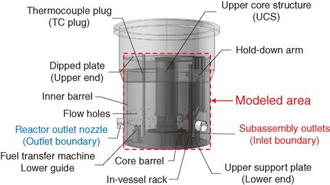
Fig.7-18 Overview of the reactor upper plenum
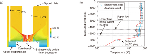
Fig.7-19 Analytical results of the temperature distribution
In fast breeder reactors (FBRs), thermal-hydraulic phenomena such as thermal stratification may cause unacceptable sodium temperature distributions under certain conditions, resulting in significant thermal stress in the components. Therefore, it is very important to evaluate thermal-hydraulics in detail. However, performing the test with a model of the same size is unrealistic because such testing would require unrealistic cost and time. Hence, an analytical method for predicting the spatial sodium temperature distribution with good accuracy should be developed. The system start-up tests under a 40% rated power operation condition were conducted in the Japanese prototype FBR, “MONJU”.
There is a large volume in the upper plenum of the reactor vessel (RV), as shown in Fig.7-18. The sodium temperature distribution in the vertical direction of the upper plenum was measured with the TC plug (Fig.7-19(b)) in these tests. Since various structures such as the UCS and the hold-down arm are installed in the plenum even under operation, the sodium thermal-hydraulic behavior is complicated. In this study, we developed a three-dimensional analysis model to accurately evaluate the thermal-hydraulics. Since the present calculation condition is steady state, the heat capacity of the structures is negligible. Therefore, we modeled only the shape of every structure except for the inner barrel in the plenum. However, the inner barrel is so thin that thermal conduction is non-negligible, and hence, it was modeled as a solid material. The RV is covered by a thermal insulator, and the amount of heat released from the RV was estimated to be very small. Therefore, the RV wall was modeled as being adiabatic. The flow rates and outlet temperatures of all subassemblies were estimated based on the measured total flow rate of the primary heat transport system, and they were set as the inlet boundary conditions of this analytical model. The measured data were compared with the analytical results for the validation. The analytical results and the measured temperature are shown in Fig.7-19. The range of error bars is twice the standard deviation of the observed temperature fluctuation. From the analysis result, it was found that the lower temperature sodium stagnated over the upper support plate (Fig.7-19(a)), and the analytical results agreed well with the measured data (Fig.7-19(b)). Thus, it is estimated that the present analysis model is applicable for predicting the thermal-hydraulics of the RV upper plenum under the present conditions.
We are going to perform analyses of the plant trip test from the 40%-rated operational conditions to validate the present analytical model and evaluate the thermal stratification behavior as a future subject.
<Previous: 7-6 | Next: 8 Research and Development Related to the Backend of the Nuclear Fuel Cycle and the Reprocessing of Spent Nuclear Fuel >

