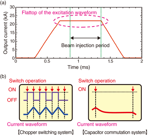
Fig.5-5 (a) Trapezoidal waveform of a pulsed power supply and (b) current waveform-formation methods using pulsed power supplies of different circuit configurations (blue: chopper-switching system, red: capacitor-commutation system)
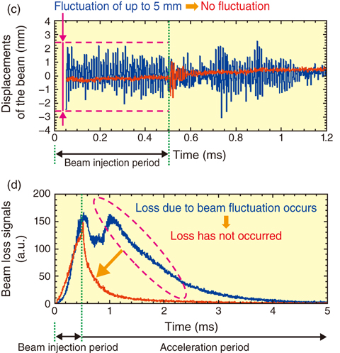
Fig.5-6 (c) Beam-orbit displacements and (d) beam-loss signals with a beam intensity of 550 kW (blue: chopper-switching system, red: capacitor-commutation system)
Located at the Japan Proton Accelerator Research Complex (J-PARC), the 3 GeV Rapid Cycling Synchrotron (RCS) accelerates injected protons up to 3 GeV with a repletion rate of 25 Hz and is intended to output a 1-MW beam power. The injection-pulsed magnets of the RCS control the injection-beam orbit using the flat tops of the trapezoidal waveform (Fig.5-5(a))and merge the many protons into a circulating beam.
The original pulsed power supply adopted a chopper-switching system for the main circuit, which formed the trapezoidal waveform by continuous ON/OFF-switching operation of the semiconductor switch (Fig.5-5(b): left). Thus, an arbitrary waveform change was possible and various injection parameters were produced in an acceleration-beam test. However, the continuous current ripple caused by the switching operation caused beam fluctuation (Fig.5-6(c): blue) and beam loss occurring owing to beam instability was observed during beam power ramp-up (Fig.5-6(d): blue).
We paid attention to ensure that the output current of the trapezoidal waveform of the capacitor-commutation system switched only three times per period. The power supply adopting this system is suitable for eliminating current ripple (Fig.5-5(b): right) during the beam-injection period. However, this current-waveform-formation technique is limited by the capacitance value and thus, the design of a control system is a problem that must be solved for RCS beam commissioning. In particular, distortion occurs in a flattop owing to an eddy current effect when the rise time of the waveform is changed.
To decide the basic capacitance value of the capacitor-commutation system, we constructed an equivalent circuit model by understanding the characteristic of the load exactly and analyzed it using circuit simulation. In addition, we devised a new correction circuit capable of controlling the waveform and realized high flattop flatness. Furthermore, in order to reliably reduce current ripple, we worked to reduce high-frequency noise due to the current route of the main circuit.
According to our results, various injection parameters could be produced. Thus, high-accuracy trajectory control without fluctuation has been realized (Fig.5-6(c): red) and a significant reduction of beam loss has been demonstrated (Fig.5-6(d): red). Consequently, there is a prospect of realizing stable user operation with a 1-MW high-intensity proton beam.

