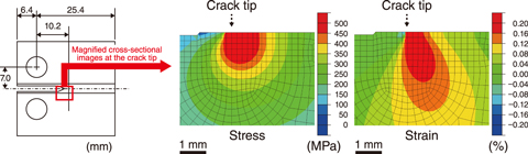
Fig.2-9 Configuration of a CT specimen and contour figures of stress and strain near a crack tip in a 7-kN loaded CT specimen (K = 30 MPa(m)1/2) immersed in a simulated BWR coolant condition
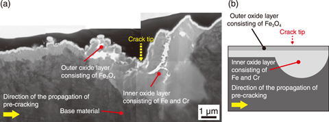
Fig.2-10 A cross-sectional image obtained by TEM (a) and a schematic illustration (b) near a crack tip for a 7-kN loaded CT specimen (K = 30 MPa(m)1/2) immersed in a simulated BWR coolant condition for 224 hours
Environmentally-assisted cracking (EAC) is known as a significant degradation issue for stainless steels used in primary coolant loops and core internals subjected to high-temperature and high-pressure water (∼300 ℃) in light-water reactors. This cracking is induced in susceptible materials by welding, tensile residual stress, and a corrosive environment. The detailed mechanism of crack propagation has not yet been clarified. Tensile stress, which is known as a parameter that enhances crack propagation, may promote local plastic strain near a crack tip (see the red region of the finite element analysis (FEA) shown in the right figure of Fig.2-9). The effect of plastic strain on EAC is not understood well. Efforts were therefore made to focus on the role of local strain induced by tensile stress during oxidation around crack tips and the propagation of EAC. To do so, an immersion test was performed under a simulated boiling water reactor (BWR) coolant condition at 290 ℃ and 9 MPa (10 μS/m in conductivity) using compact tension (CT) specimens made of a 316L stainless steel to produce oxide layers inside cracks. During the immersion test, a 7-kN constant load was applied to the specimens to cause stress concentration at a crack tip in the specimens. Here, the stress intensity factor, K, (a parameter that represents the driving force for crack growth) at the crack tip of a fatigue pre-crack was set to 30 MPa(m)1/2. Detailed observations of oxide layers near crack tips were performed using a transmission electron microscope (TEM) after the immersion test.
As shown in Fig.2-10, an outer oxide layer consisting of magnetite (Fe3O4) and an inner oxide layer containing iron (Fe) and chromium (Cr) were observed inside the cracks in the immersed specimens. The characteristically thick inner layer was produced near the crack tip in loaded specimens (see Fig.2-10(a)). The thick oxide layer near the crack tip indicates that oxygen diffuses from the bulk water into the crack. However, the gap size of the crack during this immersion test was estimated to be less than 1 μm by FEA. This narrow gap would inhibit the diffusion of oxygen dissolved in water to the crack tip, thus suppressing the oxide growth at the crack tip. The inner oxide layer observed in this study (0.3 μm after a 50-hour immersion) was much thicker than that observed in a previous study using unloaded specimens with a similarly narrow gap (0.09 μm after a 1000-hour immersion). Considering the strain near the crack tip simulated by FEA in Fig.2-9, dislocations, which are induced by the tensile stress, were concluded to provide diffusion paths for oxygen atoms.
Future work will consist of crack growth rate tests to investigate effects of the thick oxide layer near crack tips induced by tensile stress on crack propagation. These experimental results and new findings will allow for a better understanding of the mechanism of EAC to confirm the conservativeness of the current integrity assessment method for EAC.
A part of this study was conducted in FY2013 and FY2014, sponsored by the Nuclear Regulation Authority (NRA), Japan.
(Kuniki Hata)

