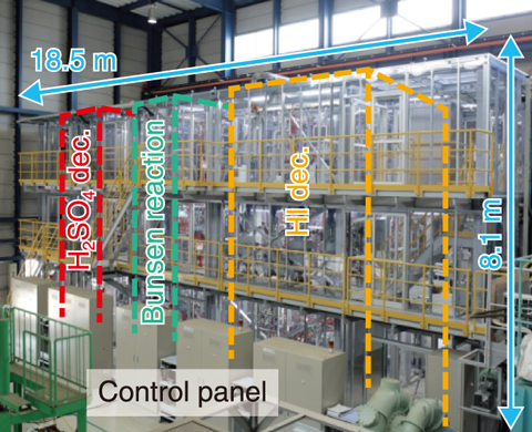
Fig.6-14 External view of hydrogen production test facility
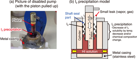
Fig.6-15 Pump malfunction during a hydrogen production test
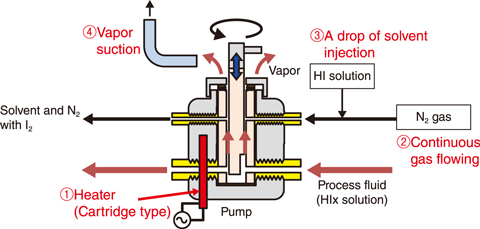
Fig.6-16 Development of shaft seal technology
The thermochemical water-splitting IS process offers a potential heat-application technologies of HTGRs. Due to the high required reaction temperature of 900 ℃ and highly corrosive fluids involved, such as sulfuric acid, iodine (I2) and hydrogen iodide (HI), all components must be made of industrial materials with high corrosion and heat resistance. A hydrogen production test facility has been constructed in 2013 (Fig.6-14); since then, a series of continuous hydrogen production tests have been performed to verify the integrity of all IS process components and control methods of the closed IS process.
For example, an 8-hour hydrogen production test was performed with a hydrogen production rate of 10 L/h in 2016. However, a pump containing a solution of HI with a high concentration of I2 was stopped during operation. Solid I2 was observed on the piston surface of the disabled pump, as shown in Fig.6-15(a). The pump malfunction was likely caused by leakage of process fluid containing I2 near its solubility limit into the narrow gap between the piston and cylinder, where I2 was then precipitated due to a decrease in temperature and/or a change in chemical composition. The precipitated I2 caused an increase in the slide friction, causing the pump to eventually stop (Fig.6-15(b)).
To prevent I2 precipitation in the narrow gap, a shaft seal technology was developed by injecting gas and liquid into the narrow gap to flush out solid I2 (Fig.6-16). This developed shaft seal included four components: ① a heater for preventing I2 precipitation due to the decrease in temperature, ② an inert gas flow to purge the process fluid and solvent from the gap, ③ the injection of a small amount of solvent (HI solution) to dissolve I2 that had precipitated in the gap, and ④ vapor suction to remove the leakage from the top side of the pump. The pump equipped with the developed shaft seal technology was then verified under conditions similar to those when the pump stopped functioning. The modified pump worked continuously and stably for 24 h, thus confirming the effectiveness of the developed shaft seal technology. This technology has been applied to the pumps used in the hydrogen production test facility, where hydrogen production was then conducted successfully for 31 hours with a hydrogen production rate of approximately 20 L/h.
The introduction of a composition adjustment method of Bunsen solution to the facility based on findings from continuous operation is underway. Future work will involve operational data collection and analysis of component reliability for the practical application of the IS process.
(Hiroki Noguchi)

