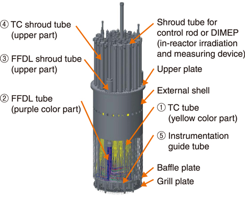
Fig.7-2 Major components of the above-core structure (ACS) and arrangement of the instrumentation tubes in the 3D-CAD study
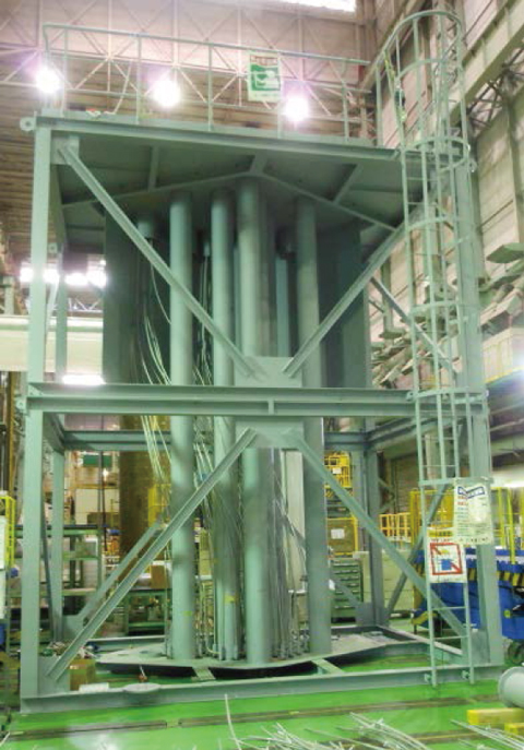
Fig.7-3 Mock-up experiment
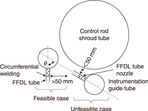
Fig.7-4 Weldability schematic of the FFDL tube nozzle
In a sodium-cooled fast reactor (SFR), several tubes are installed above each fuel subassembly to monitor the core. The above-core structure (ACS) is a structure designed to support the control rod drive mechanisms and instrumentation systems, such as thermocouples (TCs) and the failed fuel detection and location (FFDL) system, each with their various tubing and materials, in an SFR. The complexity of the integration of said systems has been identified as an issue in ACS development. This work therefore aimed to perform a routing study for TC and FFDL tubing using 3D modeling and a mock-up design of the ACS to clarify the integration process. This work was done as part of an SFR collaboration program between France and Japan.
The resulting arrangement of the tubes from the 3D-CAD study, designed for feasibility in assembly and for worker access, is shown in Fig.7-2. Here, the TC tubes (① in Fig.7-2) and FFDL tubes (② in Fig.7-2) were first divided into a few parts in the axial direction in consideration of the assembling process. To secure a work space, the assembling work of the instrumentation tubes has to be progressed from the center toward the outside of the ACS; the 702 instrumentation tubes and shroud tubes (③ and ④ in Fig.7-2, respectively) were thus designed.
The designed arrangement was then built in a mock-up at one-third partial full-scale based on the 3D-CAD study, as pictured in Fig.7-3. Although the TC and FFDL tubes did not contact each other in the 3D-CAD study, some contacts were found in the mock-up experiment. These contacts were attributed to manufacturing dimensional tolerances caused by the necessary bending of the long, straight tubes into the required complex shapes. Re-evaluation of the 3D-CAD study including the implementation of the manufacturing dimensional tolerances is a promising solution.
The welding torches used in the mock-up experiment need at least 50 mm around the welding line of the tube. However, in some areas, the distance between the FFDL tube nozzle and the instrumentation guide tube (⑤ in Fig.7-2) was less than 50 mm, depending on the horizontal orientation of the guide tube. Welding between the FFDL tube nozzle and the FFDL tube was therefore impossible at these points. To address this issue, future work will involve evaluating the appropriate range of the FFDL tube nozzle orientation to ensure the necessary space for welding, as shown in Fig.7-4. The arrangement of the tubes should then be re-evaluated based on this range.
The performed CAD study and partial-full-scale mock-up will aid in the development of fabrication and manufacturing efforts for the design of the ACS.
This study is part of the results conducted on “Technology development program of fast reactor international cooperation, and others”, supported by the Agency for Natural Resources and Energy (ANRE), the Ministry of Economy, Trade and Industry (METI), Japan.
(Kazuya Takano)
<Previous: 7 Research and Development of Fast Reactors | Next: 7-2>

