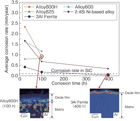
Fig.6-9 Average corrosion rate change with the increasing corrosion time of each material and Al map of the oxide film/matrix cross-section in Alloy800H and 3Al Ferrite

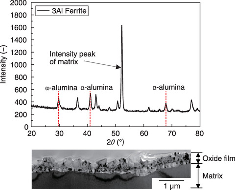
Fig.6-10 Surface structural analysis by X-ray diffraction with 3Al Ferrite and TEM-magnified observation photograph of the cross-section of the same material
The iodine sulfur (IS) process, which is a thermochemical hydrogen production method that is a potential heat-application technology of high temperature gas-cooled reactors, treats highly corrosive hydrogen iodide (HI) and sulfuric acid at high temperature. Any material involved in the process must have excellent heat and corrosion resistance. In particular, the temperature inside the pressure vessel that decomposes sulfuric acid (i.e., sulfuric acid decomposer) reaches the maximum temperature in the IS process of 850 ℃. Thus, ceramics (e.g., SiC) have been considered for use as sulfuric acid decomposers.
However, assuming the operation of a practical plant that will require a large amount of hydrogen production in the future, SiC is a brittle material in addition to being difficult to increase in size due to dimensional restrictions on the sintering furnace to be manufactured and difficult welding. Therefore, we started to use metallic materials that can achieve a corrosion rate of 0.1 mm/year, which is equivalent to that of SiC.
How to form the oxide film on the matrix surface when heated at a high temperature is considered to be the key point in improving the corrosion resistance. We mainly selected the following alloys: Alloy800H; Alloy825, an iron (Fe)-based alloy that forms an Fe and chromium (Cr) oxide film; 3Al Ferrite, a ferritic stainless steel that contains a large amount of aluminum (Al) that forms an Al oxide film; Alloy600, a nickel (Ni)-based alloy that forms a Ni oxide film; and 2.4Si Ni-based alloy, which contains silicon (Si) that forms a Si-based oxide film.
In the corrosion test, a 96wt% sulfuric acid solution was heated and evaporated, then further heated to 850 ℃ to simulate an environment similar to that of an actual plant.
Fig.6-9 shows the change in the average corrosion rate with the increasing corrosion test time for each material. Alloy800H showed the worst corrosion rate after 24 h. In contrast, 3Al Ferrite was 0.42 mm/year. After 100 h, all materials had a corrosion rate lower than that after 24 h, especially 3Al Ferrite, which was 0.18 mm/year. After 400 h, the corrosion rate of 3Al Ferrite was almost the same as that of SiC.
To confirm the situation of the oxide film after the corrosion test, the Al element mapping of the film/matrix cross-section was implemented after 100 h of Alloy800H, which was severely corroded, and after 400 h of 3Al ferrite, which had excellent corrosion resistance. The Al layer existing under the Cr-based oxide film was completely destroyed in Alloy800H, while a uniform-thickness Al layer was formed in 3Al Ferrite. Fig.6-10 shows the surface structural analysis by X-ray diffraction after the corrosion test on 3Al Ferrite and the magnified microstructure observation photograph of the cross-section of the same material with a transmission electron microscope (TEM). The intensity peaks of the ferrite phase of the matrix and α-alumina of the oxide film were detected by X-ray diffraction. The TEM observation of the same material confirmed a dense 1 µm-thick oxide film without gaps. In short, the excellent corrosion resistance of 3Al Ferrite was caused by the uniform formation of α-alumina on the matrix surface.
This research is a part of the result of the joint research “Research on corrosion resistant alloy development in IS process environment” with Nippon Steel Corporation.
(Noriaki Hirota)