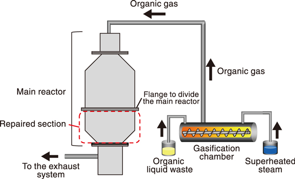
Fig.1 Diagram of the main reactor and repaired section
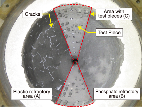
Fig.2 Overhead view of the repaired area after the repair and treatment process
Radioactive organic liquid wastes containing high concentrations of fluorine and chlorine that originated from the dismantling of equipment has been stored at the JAEA. These wastes are not suitable for incineration. We have developed a steam reforming treatment system that can decompose such flame-retardant waste into combustible organic gases by using superheated steam.
Fig.1 shows a diagram of the steam reforming treatment system. The main reactor, which burns organic gases, shows cracks and flaking of the refractory caused by age-related deterioration, and hence, it requires repairs. To select the appropriate repair material, two materials−plastic refractory and phosphate refractory− were evaluated. These materials have the same composition and thermal properties as the main reactor refractory. The plastic and phosphate refractory materials were applied to areas (A) and (B) of the main reactor, respectively, as shown in Fig.2. To determine the typical tensile strength and hardness values of the repair materials, some test pieces comprising 1-cm-thick cylindrical repair materials were attached to area (C). After applying the repair materials, a heat treatment process was conducted for sintering the repair materials for 4 h at a maximum temperature of 1200 ℃ inside the main reactor; these conditions are identical to those in an actual steam reforming treatment process.
To evaluate the applicability of the repair material, we conducted tensile strength measurements of the main reactor refractory and test pieces, hardness measurements of the test pieces, and visual inspections of the repair material.
The tensile strength is the vertical force required to detach a test piece. The tensile strength was 0.9 N/mm2 for the plastic refractory and 0.45 N/mm2 for the phosphate refractory. These values exceed the general construction standard of tensile strength of 0.4 N/mm2. Thus, the adhesion of each repair material is satisfactory.
After tensile strength measurements, the test pieces were detached from the main reactor, and hardness measurements were performed. The results showed that there was no decrease in the hardness of either repair material.
The visual inspection after the treatment showed that the plastic refractory area (A) had cracks and flaking throughout, while the phosphate refractory area (B) had only a few small cracks on the surface of the repair material, as shown in Fig.2. This indicates that the plastic refractory repair method is inappropriate and that the phosphate refractory repair method is effective for repairing the main reactor refractory.
With the establishment of repair methods for the main reactor and the prospect of stable use of the main reactor, the steam reforming treatment system is approaching the stage of its practical application. We plan to conduct a long-term heat treatment test for the practical application of this system.
(Jun Kijima)

