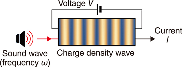
Fig.1 Schematic diagram of ultrasound detection using a charge density wave
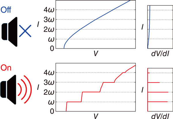
Fig.2 Current-voltage characteristics of the charge density wave
Sound waves propagate in water and solids more easily than electromagnetic waves, and they are widely used in devices such as fish finders and touch panels, as well as procedures such as abdominal ultrasonography. Recently, the use of the sound wave as an information medium for quantum information technology was explored. Sound waves may replace some information media based on light and electrons. To achieve this, it is necessary to detect sound waves with high sensitivity.
We proposed to use a charge density wave (CDW) for sound wave detection (Fig.1). A CDW is an ordered state in which the electron density and crystal lattice are modulated simultaneously with a certain periodicity. In the CDW state, the current (I)-voltage (V) characteristic is nonlinear, as shown by the blue line in the upper central panel of Fig.2. When voltage V is applied, a current I begins to flow if the voltage exceeds a certain value. We theoretically reproduced this behavior by considering an impurity pinning of the CDW. The voltage at which a current begins to flow corresponds to depinning, which allows the CDW to slide through the crystal, resulting in a current-flowing state. The mechanism of the sliding mode of the CDW is different from electrical conduction in metals.
When sound waves are added to the sliding CDW, the I−V characteristic takes a stepped appearance, as indicated by the red line in the lower central panel of Fig.2. Moreover, the staircase-like changes appear during a certain period, and the intervals between the steps are multiples of the frequency (ω) of the sound wave. This phenomenon is considered to be a synchronization caused by interference between the sliding motion of the CDW and the oscillating motion of the sound wave. In an experiment, this change was measured in terms of resistance (dV/dI) for easy visualization (the rightmost panels in Fig.2). The step-like changes appear as sharp peaks. Since these peaks appear only at currents with frequencies that are multiples of ω, the difference between the results obtained with (On) and without (Off) sound waves is obvious. Moreover, since these changes are abrupt and sharp, we expect that the sound waves can be measured with high sensitivity. Another possible use of this phenomenon is to determine the value of ω from the intervals of the peaks.
Electronics is developing toward spintronics, in which the magnetism (i.e., spin) of electrons is applied to electronics. The conversion of a spin current (i.e., magnetic flow) into a sound wave is being studied by many researchers because the sound wave has an advantage over spin current with regard to transmission over long distances. We expect that our results will drive the development of the latest technologies, and that sound waves will play a role in information technology in the future.
This work was supported by JSPS KAKENHI Grant-in-Aid for Scientific Research (C) (JP20K03810) and Grant-in-Aid for Scientific Research (S) (JP21H04987).
(Michiyasu Mori)

