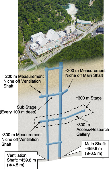
Fig.14-25 Layout of the Mizunami Underground Research Laboratory
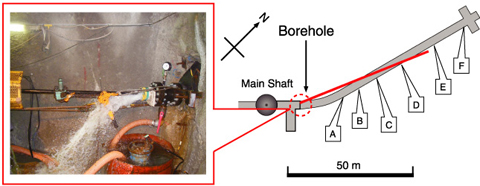
| Fig.14-26 Water inflow from borehole | Fig.14-27 -300 m Access/Research Gallery (Horizontal tunnel) | |
| The rate shown in this photograph was about 1200 liters per minute. | Borehole investigation (62.5 m long) was conducted before excavations began. |
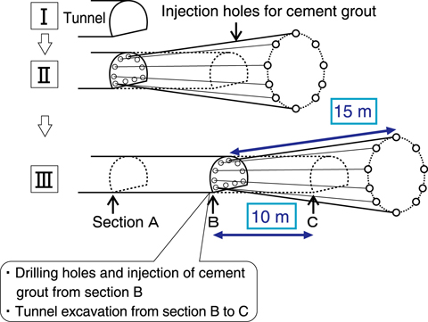
Fig.14-28 Pre-excavation grouting and tunnel excavation pattern
The Mizunami Underground Research Laboratory, one of the main facilities in Japan for research and development of the technology for high-level radioactive waste disposal, is under construction in Mizunami City. As of March 2010, the excavation of the Main and Ventilation Shafts had reached GL -459.6 m and -459.8 m, respectively (meters below ground level, Fig.14-25).
In planning the construction, it was necessary to obtain more reliable information on the bedrock conditions in terms of the rock mass stability and hydrogeology, and therefore borehole investigations were conducted before excavations began. The results indicated that a large water inflow could be expected during the excavation of the Ventilation Shaft at around GL -200 m and from -400 m to -450 m and near the -300 m Access/Research Gallery. In order to mitigate against water inflow, pre-excavation grouting was conducted before excavation of shafts and research tunnels. Grouting refers to the injection of a material such as cement into a rock mass to stabilize and seal the rock. Our report described pre-excavation grouting and construction at the GL -300 m Access/Research Gallery.
Borehole investigations were also conducted before tunnel excavation in order to get reliable information on the bedrock conditions (Fig.14-27). The borehole drilling produced water at an inflow rate of about 1000 liters per minute (Fig.14-26). Injection holes for cement grout were drilled to a length of about 15 m, and cement grout was injected into the injection holes. Tunnel was excavated to a length of about 10 m after injection. The grouting and tunnel excavation steps were then repeated (Fig.14-28). Geological mapping during the excavation confirmed the successful injection of cement grout into the fractures. The water inflow through the grouted rock mass was reduced considerably.
In planning the construction, the water inflow reduction target was established by theoretical analysis of groundwater flow in terms of the bedrock conditions. The pre-excavation grouting was shown to be successful in subsequent excavations, and the targeted reduction was achieved. The results suggest that this methodology is effective in reducing water inflow.