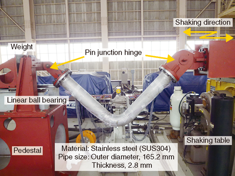
Fig.7-5 Test setup for a dynamic failure test of the elbow

Fig.7-6 Comparison between (a) the test observation at the crown part of the elbow and (b) the analytical result using finite element analysis
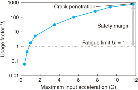
Fig.7-7 Fatigue evaluation based on a design code for piping
To ensure the seismic integrity of nuclear power plants, both confirming the ultimate strength under a high-level earthquake beyond the design condition and clarifying the design safety margin up to ultimate strength have been focused as important issues. In this study, a dynamic test of an elbow for a sodium-cooled fast reactor was performed based on the knowledge that stress is easily concentrated into elbows in piping.
In the test, using a pin junction, one end of the elbow was fixed to a shaking table and a weight was fixed at the other end of the elbow (Fig.7-5). Excitation of the shaking table imposed an in-plane bending moment on the elbow by the inertial load of the weight. The results showed that the elbow did not fail under an earthquake of the level for which it was designed. After the confirmation, the excitation level was scaled up and the test was continued to confirm the ultimate behavior of the elbow. High-level excitation significantly exceeding the design level was needed to cause the elbow to fail in the test. Finally, a crack in the axial direction was observed at both sides of the crown part of the elbow (Fig.7-6(a)). It was confirmed from the test that the failure mode of the elbow was low cycle fatigue with crack initiation, propagation, and through-wall penetration. No structural instability such as collapse was observed. Moreover, it was confirmed that finite element analysis can be used to reproduce the failure behavior of the elbow (Fig.7-6(b)).
Fatigue evaluation of the test based on the design code for piping was performed to clarify the safety margin included in the design fatigue evaluation method. The calculated usage factor (a usage factor shows the state of fatigue damage of a structure, with a usage factor of 1 being defined as fatigue failure of the structure) was significantly beyond unity when the elbow actually failed (Fig.7-7). This result indicates that the conventional method of evaluating fatigue in piping has a large safety margin.

