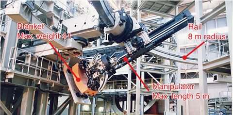
Fig.9-2 Prototype of the ITER remote-handling robot
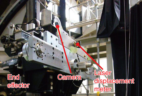
Fig.9-3 Camera(s) used for robot vision
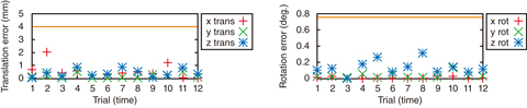
Fig.9-4 Robot vision positioning errors
A component called a “blanket” is installed in fusion reactors to prevent damage to the vacuum vessel caused by heat or radiation. The blanket in ITER is divided into 440 modules, some weighing up to 4 t. The blanket must be replaced, but as the radiation level inside the vacuum vessel will be 250 Gy/h (owing to γ-rays), the only way the blanket modules can be exchanged is by using remote-handling equipment. We have been developing a robot for this purpose. The robot uses a large manipulator that travels along a rail and was designed to be able to reach all areas of the vacuum vessel (Fig.9-2). The manipulator must be positioned in front of the blanket module to within 4 mm in translation error and 0.76° in rotation error in order to grasp the blanket modules. Positioning must be performed through a non-contact method, so as not to damage the surface of the blanket. The conventional method using laser-displacement meters cannot be applied here as these meters contain semiconductors that are susceptible to radiation. That is why we developed and tested a positioning method based on image processing with imaging-tube analog cameras having a radioresistance of approximately 2 MGy. This control method is called robot vision.
Our method uses camera(s) that are installed at the end of the manipulator (the end effector) (Fig.9-3). By processing the images of the blanket obtained with this camera, we can calculate the position of the manipulator relative to the blanket. The manipulator is then positioned based on this calculation. Since the resolution of the imaging tube is low, approximately 500 scanning lines, the images were grainy and caused an issue with positioning accuracy. To resolve this, we used two cameras and compared the image data from each to perform our calculations, improving accuracy.
Tests were performed to evaluate errors in positioning of the manipulator using the methods we developed. The positioning errors were measured using a laser-displacement meter installed at the end effector (Fig.9-3). The biggest errors were 2.0 mm in translation and 0.31° in rotation, confirming that there is sufficient positioning accuracy to grasp the blanket modules (Fig.9-4).
We confirmed that robot vision is a suitable method for positioning the manipulator in radioactive environments. We intend to develop a control method that not only automatically positions the manipulator with respect to the blanket but also grasps the blanket module automatically by combining robot vision with force sensors or the like.
<Previous: 9 Nuclear Fusion Research and Development | Next: 9-2>

